I. SD-SDI
기준 신호는 SMPTE 259M-2008 (SDTV1 Digital Signal/Data — Serial Digital Interface)에 따르며 아래 표1의 규격에 준한다. (상세 규격 내용은 첨부의 SMPTE 259M-2008을 참조) Jitter의 측정 및 규격은 SMPTE 259M-2008 및 SMPTE RP 184(Specification of Jitter in Bit-Serial Digital Systems)에 따르며 아래 표1의 규격에 준한다.
시험 장치 및 계측 장비 사이에는 고품질의 짧은 케이블(일반적으로 1m/3ft.)을 사용하여 노이즈 효과 및 주파수 롤 오프를 영향을 받지 않도록 한다. 테스트 신호발생장치는 스트레스 없는 테스트 신호인 컬러 바 신호 패턴을 생성해야 한다.
II. HD-SDI
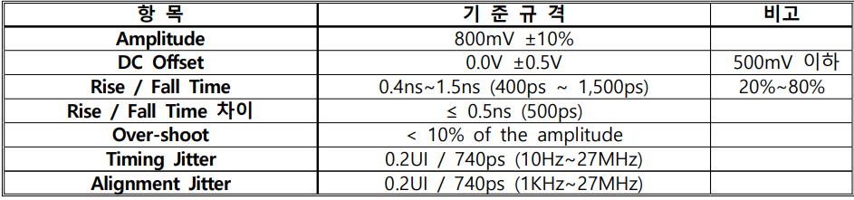
기준 신호는 SMPTE 292M-2008 (1.5 Gb/s Signal/Data Serial Interface)에 따르며 아래 표2의 규격에 준한다. (상세 규격 내용은 첨부의 SMPTE 292M-2008을 참조) Jitter의 측정 및 규격은 SMPTE 292M-2008 및 SMPTE RP 184(Specification of Jitter in Bit-Serial Digital Systems)에 따르며 아래 표2의 규격에 준한다.

시험 장치 및 계측 장비 사이에는 고품질의 짧은 케이블(일반적으로 1m/3ft.)을 사용하여 노이즈 효과 및 주파수 롤 오프를 영향을 받지 않도록 한다. 테스트 신호발생장치는 스트레스 없는 테스트 신호인 컬러 바 신호 패턴을 생성해야 한다.
III. 아날로그 오디오
- LINE : 기준 입력 레벨:+4dBu/최대입력레벨:+24dBu
- MIC : 기준 입력 레벨:-60 ~ -20dBu/최대입력레벨:0dBu , 감도는, 규정 레벨(+4dBu)의 출력을 얻을 수 있는 최소 입력 레벨 - 0dBu : 0.775Vrms; -0dBV : 1Vrms
- LINE : 기준 입력 레벨:+4dBu/최대입력레벨:+24dBu
- 모든 음향신호의 라인 레벨은 +4dBu를 기준레벨로 하며 음향기기의 접속 시에도 +4dBu를 기준으로 한다.
- 음향신호의 객관적 레벨 모니터는 VU미터를 기준으로 하며 0VU(Volume Unit)는 +4dBu로 세팅한다.
- 프로그램의 평균 음향레벨은 -1VU가 되도록 하며 모든 음향신호는 -5VU∼+2VU 사이에 위치하도록 한다.
- 프로그램 제작 시 타이틀 레벨은 -2VU, CM은 -4VU, 본 내용은 0VU∼-5VU를 기본으로 한다.
IV. DIGITAL AUDIO – AES INTERFACE
기준 신호는 EBU TECH 3250 (Specification of the digital audio interface 중 Line driver characteristics)에 따르며 아래 표3의 규격에 준한다.

시험은 1KHz –20dBFS (SMPTE Scale)의 신호를 기준신호로 사용하여 시스템 및 장비를 통과 후 신호의 레벨과 위상을 측정한다. 이때 전기적 특성은 상기의 표 3을 기준으로 한다.
V. DIGITAL AUDIO – AES3id INTERFACE
기준 신호는 AES-3id-2001 (AES information document for digital audio engineering — Transmission of AES3 formatted data by unbalanced coaxial cable 중 Line driver characteristics)에 따르며 아래 표4의 규격에 준한다.

시험은 1KHz –20dBFS (SMPTE Scale)의 신호를 기준신호로 사용하여 시스템 및 장비를 통과 후 신호의 레벨과 위상을 측정한다. 이때 전기적 특성은 상기의 표 4을 기준으로 한다.
VI. SDI EMBEDDED DIGITAL AUDIO
기준 신호는 SMPTE 259M-2008과 SMPTE 292M-2008의 규격에 준하며 신호의 기준 및 규격은 별도 명시를 하지 않는다.
HD-SDI Embedded 신호의 경우에는 SMPTE 292M-2008, SD-SDI Embedded 신호의 경우에는 SMPTE 259M-2008의 기준을 따르며 각 비디오 신호 표준 신호에 1KHz –20dBFS(SMPTE Scale)의 신호가 포함된 SDI Embedded 기준신호를 해당 시스템 및 장비에 통과 시킨 후 신호의 레벨과 위상을 측정한다. 이때 신호는 기준 신호와 동일하여야 한다.
첨부 1) SMPTE 259M-2008 (SDTV1 Digital Signal/Data - Serial Digital Interface) 발췌
8. Coaxial Cable Interface
8.1 Signal Levels and Specifications
These specifications are defined for measurement of the serial output of a source derived from a parallel domain signal.
8.1.1 The output of the generator shall be measured across a 75-ohm resistive load connected through a 1-m coaxial cable. Figure 4 depicts the measurement dimensions for amplitude, rise-time and overshoot.

8.1.2 The generator shall have an unbalanced output circuit with a source impedance of 75 ohms and a return loss of at least 15 dB over a frequency range of 5 MHz to the clock frequency of the signal being transmitted.
8.1.3 The peak-to-peak signal amplitude shall be 800 mV ± 10% measured as specified in § 8.1.1.
8.1.4 The dc offset, as defined by the mid-amplitude point of the signal, shall be nominally 0.0 V ± 0.5 V.
8.1.5 The rise and fall times, determined between the 20% and 80% amplitude points shall be no greater than 270 ps and shall not differ by more than 100 ps.
8.1.6 Overshoot of the rising and falling edges of the waveform shall not exceed 10% of the amplitude
8.1.7 Output amplitude excursions due to signals with a significant dc component occurring for a horizontal line (pathological signals) shall not exceed 50 mV above or below the average peak-to-peak signal envelope. Note this specification defines a minimum output coupling time constant.
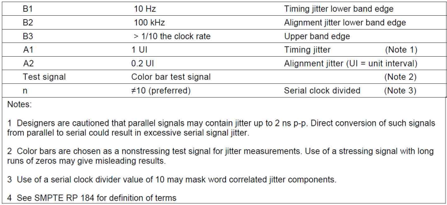
8.1.8 The jitter in the timing of the transitions of the data signal shall be measured in accordance with SMPTE RP 184. Measurement parameters are defined in SMPTE RP 184 and shall have the values shown in Table 3 for compliance with this standard.
8.1.9 The receiver of the serial interface signal shall present an impedance of 75 ohms with a return loss of at least 15 dB over a frequency range of 5 MHz to the clock frequency of the signal being transmitted.
8.1.10 Receivers operating with input cable losses in the range of up to 20 dB at one-half the clock frequency are nominal; however, receivers designed to work with greater or lesser signal attenuation are acceptable.
8.1.11 When connected to a line driver operating at the lower limit of voltage permitted by § 8.1.3, the receiver must sense correctly the binary data in the presence of the superimposed interfering signal at the following levels:
dc ± 2.5V
Below 5 kHz <2.5V p-p
5 kHz to 27 MHz <100 mV p-p
Above 27 MHz <40 mV p-p
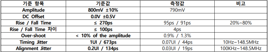
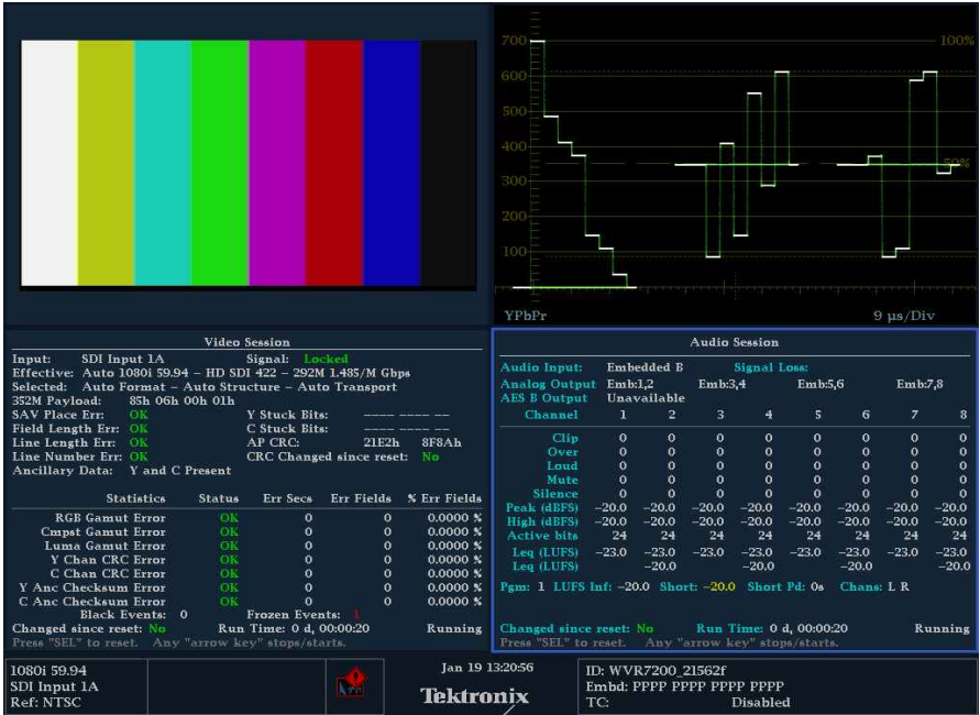
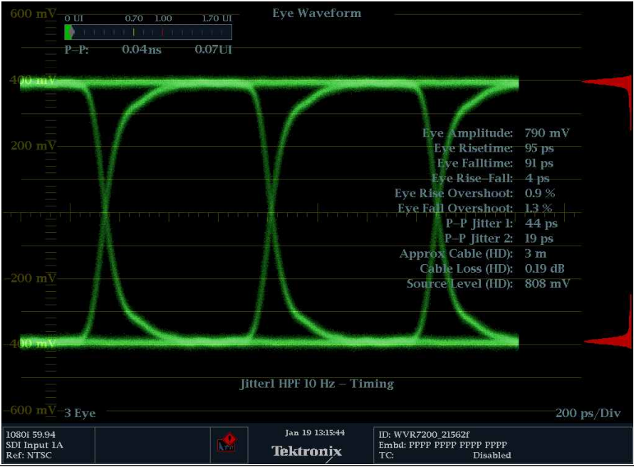
첨부 2) 측정 예제 (기준신호 Tektronix SPG8000 Color Bar)
'방송 기술 > IP기반 방송' 카테고리의 다른 글
| SMPTE ST 2110 신호란? (0) | 2022.01.10 |
|---|---|
| IP 기반 방송에서 성공적인 모니터링을 위한 열쇠 (0) | 2021.11.25 |
| IP 기반 방송신호 모니터링 (0) | 2021.11.25 |
| 방송 IP 전환 보고서 2021_방송 산업의 IP 및 클라우드 도입 현황 (0) | 2021.11.25 |